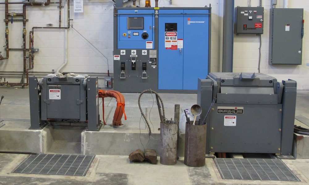
A power supply is a frequency converter from static line to medium/high frequency. Industrial electricity is usually available in line frequency, 3-phase, while high-frequency power is required to power the induction heating equipment.
The static power supply conditions adequate incoming power to power the heat/fusing application. The power supply also has the ability to regulate the power supplied to the coil, in addition to switching on and off and protecting the vital semiconductor components used.
As shown in the block diagram, the 3-phase input supply feeds the 3-phase full wave thyristor controlled rectifier to convert the AC supply to DC. An LC filter filters the high frequency waves that return to the electrical network.
The transistorized inverter converts the direct current supply to alternating current. Varying the switching frequency of the inverter will change the output power. The switching frequency of the inverter is automatically adjusted to a required value depending on the energy demanded by the operator. When full power is called for, the switching frequency will be at its optimum value and will only be limited by the inverter voltage and current.
The Operation Of The Converter
The bridge converter with full wave thyristors is powered from the three-phase input supply through a switch/isolator and fuse assembly. The rectifier converts the AC input supply to DC and supplies it to the inverter through DC induction melting furnace supplier.
During operation, the thyristors of the converter remain turned on at maximum and thus the full DC supply remains in the inverter in the panel on state. When the main isolator/breaker is closed, the stable voltage of the DC connector ramps up to an intermediate value provided all interlocks are OK. Stepping up is done by phase control of the input rectifier when the inverter turns ON. It remains fully ‘ON’ until any interlock fails or any trip signal becomes dangerous.
The DC choke filters the rectified supply to further smooth the DC supply.
Inverter Operation
Pressing the ON button will allow the oscillator to release the pulse to the Inverter Transistors. The LC circuit starts to oscillate at the inverter’s switching frequency and draws power to the coil. Various feedback signals start to appear in the respective control sections.
The switching frequency of the inverter will be set appropriately until the required power is obtained. A small delay is provided to limit current spikes during starting or stopping. HEAT on indicator lamp lights up to indicate that high frequency induction power supply is being applied to the coil. When maximum power is required, the switching frequency is fixed at its optimum value and is only limited by the inverter voltage and the limits at that time.
